|
Thermoforming Processes
Thermoforming processes are
possible because thermoplastic sheets can be softened and
reshaped, and the new shape is retained when the material is
cooled. Most thermoplastic materials may be formed by this
process; however, acetals, polyamides, and fluorocarbons are not
usually thermoformed. Extruded, calendered, laminated, cast,
and blown films or sheet forms may be thermoformed.
Forcing a heated thermoplastic
material to take the shape of a mold by mechanical, air, or
vacuum pressure is common. Tooling costs are usually low, and
parts with large surface areas may be produced economically.
Prototypes and short runs are also practical. Although
dimensional accuracy is good, thinning is a problem in some part
designs.
Tooling can run from low-cost
plaster molds to expensive water-cooled steel molds, but the
most common tooling material is cast aluminum. Gypsum,
hardboard, pressed wood, cast phenolic resins, filled or
unfilled polyester or epoxy resins, sprayed metal, and steel
also may be used for molds.
One source dates thermoforming
back to the ancient Egyptians. They found that animal horns and
tortoise shells could be heated and formed into a variety of
vessels and shapes. In the United States, John Hyatt
thermoformed Celluloid sheets over wooden cores for piano keys.
Today, sheets and films may be
thermoformed by the basic techniques of straight vacuum forming,
drape forming, matched-mold forming, pressure-bubble plug-assist
vacuum forming, plug-assist vacuum forming, plug-assist pressure
forming, vacuum snap-back forming, pressure-bubble vacuum
snap-back forming, trapped-sheet contact-pressure forming, free
forming, and mechanical forming.
Items produced by thermoforming
include signs, light fixtures, ice-cube trays, ducts, drawers,
instrument panels, tote trays, housewares, toys, refrigerator
panels, transparent aircraft enclosures, and boat windshields.
Blister and skin packaging of products are familiar applications
of thermoforming. Replacement parts and hardware are examples of
items that are sometimes skin packaged. Skin packaging requires
no mold; the plastics film is simply formed over the product.
Cookies, pills and other products are commonly packaged by
blister packaging. Single portions of butter, jellies, and
other foods are sometimes packaged in blister packs.
1 STRAIGHT VACUUM FORMING
Vacuum forming is the most
versatile and widely used thermoforming process. Vacuum
equipment costs less than pressure or mechanical processing
equipment.
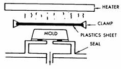
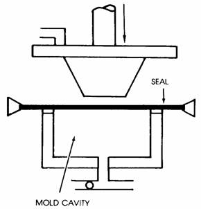
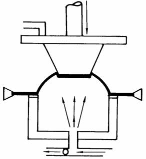
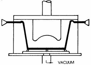
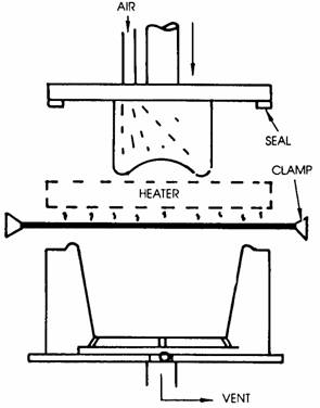
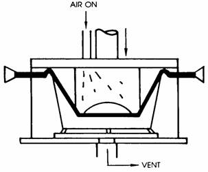
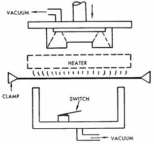
In straight vacuum forming, a
plastics sheet is clamped in a frame and heated. While the hot
sheet is rubbery, or in an elastic state, it is placed over a
female mold cavity. The air is removed from this cavity by
vacuum (Fig. 1) and atmospheric pressure (10 kPa) forces the hot
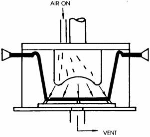
sheet against the walls and contours of the mold. When the
plastics has cooled, the formed part is removed, and final
finishing and decorating may be done, if necessary. Blowers or
fans are used to speed cooling. One disadvantage of
thermoforming is that formed pieces usually must be trimmed, and
the scrap must be reprocessed.
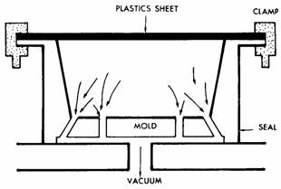
(A) A clamped and heated
plastic sheet is forced down into the mold by air pressure after
a vacuum is drawn in the mold. (Atlas Vac Machine Co.)
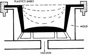
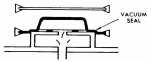
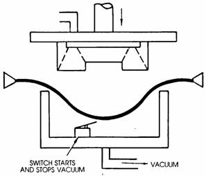
(B) Plastics sheet cools as it
contacts the mold. (Atlas Vac Machine Co.)
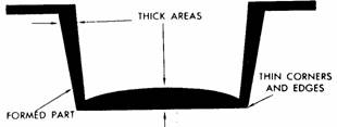
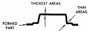
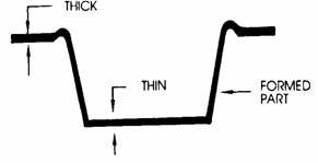
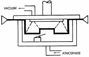
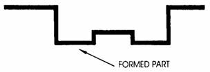
(C) Areas of the sheet that
touched the mold last are the thinnest. (Atlas Vac Machine Co.)
Fig. 1 Straight vacuum forming.
Most vacuum systems have a
surge tank to ensure a constant vacuum of 500 to 760 mm of
mercury. Superior parts are formed by quickly applying the
vacuum before any portion of the sheet has cooled. Slots are
more desirable and efficient than holes in allowing the air to
be drawn from the mold. Slots or holes should be smaller than
0.65 mm [0.025 in.] in diameter to avoid surface blemishes on
the formed part. A hole or slot should be placed in all low or
unconnected portions of the mold. If this is not done, air may
be trapped under the hot sheet with no way to escape. Unless
they are collapsible, molds should include a 2 to 7 degree angle
(draft) for easy part removal.
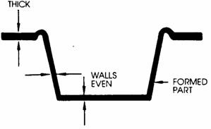
Thinning at the upper edges of
a part is a disadvantage in using relatively deep female molds.
Thinning is caused by the hot plastics sheet first being drawn
to the center of the mold. Sheeting at the edges of the mold
must stretch the most and thus becomes the thinnest portion of
the formed item. If preprinted flat sheets are formed, thinning
must be kept in mind when trying to compensate for distortion
during forming. Straight vacuum forming is limited to simple,
shallow designs, and thinning will occur often in corners.
The draw or draw ratio of a
female mold is the ratio of the maximum cavity depth to the
minimum span across the top opening. For high-density
polyethylene, the best results are achieved when this ratio does
not exceed 0.7:1. Thermoforming equipment and dies are
relatively inexpensive.
2 DRAPE FORMING
Drape forming (incorrectly
called mechanical forming) is similar to straight vacuum forming
except that after the plastics is framed and heated, it is
mechanically stretched over a male mold. A vacuum (actually, a
pressure differential) is applied that pulls the hot plastics
against all portions of the mold (Fig. 2). The sheet touching
the mold remains close to its original thickness. Side walls
are formed by the material draping between the top edges of the
mold and the bottom seal area at the base. When the plastics
has cooled, it is removed for trimming or post-processing, if
needed. Mark-off (marks from the mold) is on the inside of the
product while such marks appear on the outside of the part in
straight vacuum forming.
(A) Clamped heated plastics may
be pulled over the mold, or the mold may be forced into the
sheet.
(B) Once the sheet has formed a
seal around the mold, a vacuum is drawn to pull the plastics
sheet tightly against the mold surface.
(C) Final wall thickness
distribution in the molded part.
Fig. 2. Principle of drape
forming plastics. (Atlas Vac Machine Co.)
It is possible to drape-form
items with a depth to diameter ratio of nearly 4:1. High draw
ratios are possible with drape forming, however, this technique
is also more complex. Male molds are easy to make and, as a
rule, cost less than female ones, but male molds are more easily
damaged.
Drape forming has also been
used to form a hot plastics sheet over male or female molds by
gravitational forces alone. Female molds are preferred for
multicavity forming because there must be more spacing if male
molds are selected.
3 MATCHED-MOLD FORMING
Matched-mold forming is similar
to compression molding. A heated sheet is trapped and formed
between male and female dies that may be made of wood, plaster,
epoxy, or other materials (Fig. 3). Accurate parts with
close-tolerances may be quickly produced in costly water-cooled
molds. Very good molded detail and dimensional accuracy can be
obtained with water-cooled molds, including lettering and
grained surfaces. There is mark-off on both sides of the
finished product; therefore, mold dies must be protected from
scratches or damage because such defects would be reproduced by
the thermoplastic materials. A smooth-surfaced mold should not
be used with polyolefins because air may be trapped between the
hot plastics and a highly polished mold. Sandblasted mold
surfaces are usually used for these materials.
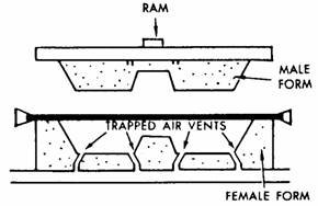
(A) The heated plastics sheet
may be clamped over the female die, as shown, or draped over the
mold form.
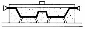
(B) Vents allow trapped air to
escape as the mold closes and forms the part.

(C) Distribution of materials
in the product depends on the shapes of the two dies.
(D) Male mold forms must be
spaced at a distance equal, to or greater than their height or
webbing may occur.
Fig. 3. Principle of
matched-mold forming. (Atlas Vac Machine Co.)
4 PRESSURE-BUBBLE PLUG-ASSIST
VACUUM FORMING
For deep thermoforming,
pressure-bubble plug-assist vacuum forming is an important
process. By this process, it is possible to control the
thickness of the formed article. The item may have uniform
thickness or the thickness may be varied.
Once the sheet has been placed
in the frame and heated, controlled air pressure creates a
bubble (Fig. 4). This bubble stretches the material to a
predetermined height, usually controlled by a photocell. The
male plug assist is then lowered forcing the stretched stock
down into the cavity. The male plug is normally heated to avoid
chilling the plastics prematurely. The plug is made as large as
possible so the plastics is stretched close to the final shape
of the finished product. Plug penetration should be from 70 to
80 percent of the mold cavity depth. Air pressure is then
applied from the plug side while at the same time a vacuum is
drawn on the cavity to help form the hot sheet. For many
products, vacuum alone is used to complete formation of the
sheet. In Figure 7-4, both vacuum and pressure are applied
during the forming process. The female mold must be vented to
allow trapped air to escape from between the plastics and the
mold.
(A) The plastics sheet is
heated and sealed across the mold cavity.
(B) Air is introduced, blowing
the sheet upward into an evenly stretched bubble.
(C) A plug shaped roughly to
the cavity contour presses downward into the bubble, forcing it
into the mold.
(D) When the plug reaches its
lowest point, vacuum is drawn to pull the plastics against the
mold walls. Air may be introduced from above to aid forming.
Fig. 4. Pressure-bubble
plug-assist vacuum forming. (Atlas Vac Machine Co.)
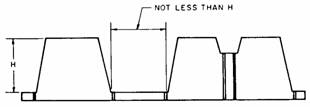
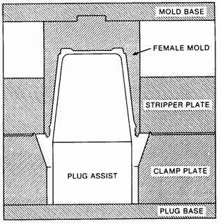
5 PLUG-ASSIST VACUUM FORMING
To help prevent corner or
periphery thinning of cup- or box-shaped articles, a plug assist
is used to mechanically stretch and pull additional plastics
stock into the female cavity (Fig. 5). The plug is normally
heated to just below the forming temperature of the sheet
stock. The plug should be from 10 to 20 percent smaller in
length and width than the female mold. Once the plug has forced
the hot sheet into the cavity, air is drawn from the mold,
completing the formation of the part. The plug design or shape
determines the wall thickness, as shown in cross-section in
Figure 5D.
(A) Heated, clamped plastics
sheet is positioned over mold cavity.
(B) A plug, shaped roughly like
the mold cavity, plunges into the plastics sheet to pre-stretch
it.
(C) When the plug reaches the
limit of its travel, a vacuum is drawn in the mold cavity.
(D) Areas of the plug touching
the sheet first form thickened areas due to chilling effect.
Fig. 5. Plug-assist vacuum
forming. (Atlas Vac Machine Co.)
Plug-assist vacuum and pressure
forming allows deep drawing, and permits shorter cooling cycles
and better control of wall thickness. Close temperature control
is needed, however, and the equipment is more complex than
straight vacuum forming (Fig. 6).
(A) Clamp layout
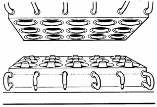
(B) RAM part clamps.
Fig. 6. Restricted-area molding
(RAM), with individual part clamps build into the mold. This
helps to control material draw and reduces draw ratio. (Brown
Machine Co.)
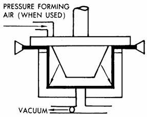
6 PLUG-ASSIST PRESSURE
FORMING
Plug-assist pressure forming is
similar to plug-assist vacuum forming in that the plug forces
the hot plastics into the female cavity. Air pressure applied
from the plug forces the plastics sheet against the walls of the
mold (Fig. 7).
(A) Heated, clamped sheet is
positioned over the mold cavity.
(B) As the plug touches the
sheet, air is allowed to vent from beneath the sheet.
(C) As the plug completes its
stroke and seals the mold, air pressure is applied from the plug
side, forcing the plastics against the mold.
(D) Plug-assist pressure
forming is capable of producing products with uniform wall
thickness.
Fig. 7. Plug-assist pressure
forming . (Atlas Vac Machine Co.)
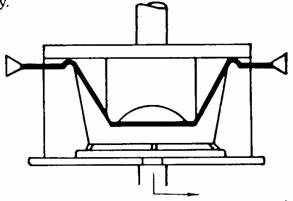
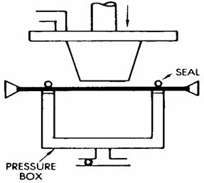
7 VACUUM SNAP-BACK FORMING
In vacuum snap-back forming,
the hot plastics sheet is placed over a box and a vacuum is
drawn that causes a bubble to be forced into the box (Fig. 8).
A male mold is lowered and the vacuum in the box is released,
causing the plastics to snap-back around the male mold. A
vacuum may also be drawn in the male mold to help pull the
plastics into place.
(A) Plastics sheet is heated
and sealed over the top of the vacuum box. (Atlas Vac Machine
Co.)
(B) Vacuum is drawn beneath the
sheet, pulling it into a concave shape. (Atlas Vac Machine Co.)
(C) The male plug is lowered
and a vacuum drawn through it. At the same time, vacuum beneath
the sheet is vented. (Atlas Vac Machine Co.)
(D) External deep draws can be
obtained with this process to form luggage, auto parts, and
other items. (Atlas Vac Machine Co.)
Fig. 8. Vacuum snap-back
forming. (Atlas Vac Machine Co.)
Vacuum snap-back forming allows
complex parts with recesses to be formed.
8 PRESSURE-BUBBLE VACUUM
SNAP-BACK FORMING
As the name implies, the sheet
is heated and then stretched into a bubble shape by air pressure
(Fig. 9). The sheet pre-stretches about 35 to 40 percent. The
male mold is then lowered. A vacuum is applied to the male mold
while air pressure is forced into the female cavity. This
causes the hot sheet to snap-back around the male mold.
Mark-off is on the male mold side.
(A) Heated plastics sheet is
clamped and sealed across a pressure box.

(B) Air pressure is introduced
beneath the sheet, causing a large bubble to form.

(C) A plug is forced into the
bubble, while air pressure is maintained at a constant level.

(D) Air pressure beneath the
bubble and a vacuum at the plug side create a uniform draw.
Fig. 9. Pressure-bubble vacuum
snap-back forming. (Atlas Vac Machine Co.)
Pressure-bubble vacuum
snap-back forming allows deep drawing and the formation of
complex parts, but the equipment is complex and costly.
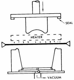
9 TRAPPED-SHEET CONTACT HEAT
PRESSURE FORMING
This process is like straight
vacuum forming except that air pressure and a vacuum assist may
be used to force the hot plastics into a female mold. Figure
7-10 shows the steps of this process.

(A) A flat, porous plate allows
air to be blown through its face.

(B) Air pressure from below and
a vacuum above force the sheet tightly against the heated plate.

(C) Air is blown through the
plate to force the plastics into the mold cavity.

(D) After forming, additional
pressure may be exerted.
Fig. 10. Trapped-sheet
contact-heat pressure forming. (Atlas Vac Machine Co.)
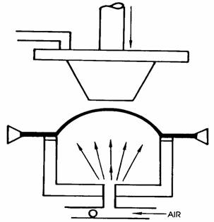
10 FREE FORMING
In free forming, air pressures
of over 2.7 MPa may be used to blow a hot plastics sheet through
the silhouette of a female mold (Fig. 11). The air pressure
causes the sheet to form a smooth bubble shaped article. A stop
may be used to form special contours in the bubble. Skylight
panels and aircraft canopies are well-known examples of this
technique.

(A) Basic setup.

(B) Air injection

(C) Examples of free-form
shapes that can be obtained with various openings. (Rohm & Haas
Co.)
Fig. 11. Free forming of
plastics bubbles.
11 MECHANICAL FORMING
In mechanical forming, no
vacuum or air pressure is used to form the part. It is similar
to matched molding; however, close-fitting matched male and
female molds are not used.
This process is sometimes
classified as a fabrication or post-forming operation. The
forming process may make use of simple wooden forming jigs to
give the desired shape using ovens, a strip heater, or heat guns
for the heat source. Flat stock may be heated and wrapped around
cylindrical shapes or stock may be heated in a narrow strip and
bent at right angles. Tubes, rods, and other profile shapes may
be mechanically formed.
12 PLASTIC PROCESSING
12.1
Injection molding
12.1.1 Process: Similar to
die casting of metals, a thermoplastic molding compound is
heated to plasticity in a cylinder at a controlled temperature
and then forced under pressure through sprues runners, and gates
into a cool mold; the resin solidifies rapidly, the mold is
opened, and the parts ejected; with certain modifications,
thermosetting materials can be used for small parts.
12.1.2 Advantages:
Extremely rapid production rate and hence low cost per part,
little finishing required; excellent surface finish; good
dimensional accuracy; ability to produce a variety of relatively
complex and intricate shapes.
12.1.3 Limitations: High
tool and die costs; high scrap loss; limited to relatively small
parts; not practical for small runs.
12.2
Cut extrusions
12.2.1 Process:
Thermoplastic molding powder is fed through a hopper to a
chamber where it is heated to plasticity and then driven,
usually by a rotating screw, through a die having the desired
cross section; extruded lengths are either used as is or cut
into sections; with modifications, thermosetting materials can
be used.
12.2.2 Advantages: Very low
tool cost; material can be placed where needed; great variety of
complex shapes possible; rapid production rate.
12.2.3 Limitations: Close
tolerances difficult to achieve; openings must be in direction
of extrusion; limited to shapes of uniform cross section (along
length).
12.3 Sheet moldings
(thermoforming) VACUUM FORMING
12.3.1 Process:
Heat-softened sheet is placed over a male or female mold; air is
evacuated from between sheet and mold, causing sheet to conform
to contour of mold. There are many
modifications, including vacuum
snapback forming, plug-assist, drape forming etc..
12.3.2 Advantages: Simple
procedure; inexpensive; good dimensional accuracy; ability to
produce large parts with thin sections.
12.3.3 Limitations: Limited
to parts of low profile.
12.4 Sheet molding
(thermoforming) BLOW OR PRESSURE FORMING
12.4.1 Process: The reverse
of vacuum forming in that positive air pressure rather than
vacuum is applied to form sheet to mold contour.
12.4.2 Advantages: Ability
to produce deep drawn parts; ability to use sheet too thick for
vacuum forming; good dimensional accuracy; rapid production
rate.
12.4.3 Limitations:
Relatively expensive; molds must be highly polished.
12.5 Sheet molding
(thermoforming) MECHANICAL FORMING
12.5.1 Process: Sheet metal
equipment (presses benders, rollers creasers. etc.) forms heated
sheet by mechanical means. Localized heating is used to bend
angles; where several bends are required, heating elements are
arranged in series.
12.5.2 Advantages: Ability
to form heavy and/or tough materials; simple; inexpensive;
rapid production rate.
12.5.3 Limitations: Limited
to relatively simple shapes.
12.6
Blow moldings
12.6.1 Process: An extruded
tube (parison) of heated plastics within the two halves of a
female mold is expanded against the sides of the mold by air
pressure; the most common method uses injection molding
equipment with a special mold.
12.6.2 Advantages: Low tool
and die cost; rapid production rate; ability to produce
relatively complex hollow shapes in one piece.
12.6.3 Limitations: Limited
to hollow or tubular parts; wall thickness difficult to control.
12.7
Slush rotational dip
castings
12.7.1 Process: Powder
(polyethylene) or liquid material (usually vinyl plastisol or
organosol) is poured into a closed mold, the mold is heated to
fuse a specified thickness of material adjacent to mold surface,
excess material is poured out, and the semifused part is placed
in an oven for final curing. A variation, rotational molding,
provides completely enclosed hollow parts.
12.7.2 Advantages: Low cost
molds, relatively high degree of complexity; little shrinkage.
12.7.3 Limitations:
Relatively slow production rate; choice of materials limited.
12.8
Compression moldings
12.8.1 Process: A partially
polymerized thermosetting resin, usually pre-formed, is placed
in a heated mold cavity; mold is closed, heat and pressure
applied, and the material flows and fills mold cavity; heat
completes polymerization and mold is opened to remove hardened
part. Method is sometimes used for thermoplastics, e.g., vinyl
phonograph records; in this operation, the mold is cooled before
it is opened.
12.8.2 Advantages: Little
waste of material and reduced finishing costs due to absence of sprues, runners, gates, etc.; large, bulk parts possible.
12.8.3 Limitations:
Extremely intricate parts involving undercuts, side draws, small
holes, delicate inserts etc., not practical, extremely close
tolerances difficult to achieve.
12.9
Transfer moldings
12.9.1 Process: Used
primarily for thermosetting materials, this method differs from
compression molding in that the plastic is 1) first heated to
plasticity in a transfer chamber, and 2) fed, by means of a
plunger, through sprues, runners, and gates into a closed mold.
12.9.2 Advantages: Thin
sections and delicate inserts are easily used; flow of material
is more easily controlled than in compression molding; good
dimensional accuracy; rapid production rate.
12.9.3 Limitations: Molds
are more elaborate than compression molds and hence more
expensive; loss of material in cull and sprue; size of parts
somewhat limited.
12.10 Reinforced plastics
moldings CONTACT
12.10.1 Process: The
lay-up, which consists of a mixture of reinforcement (usually
glass cloth or fibers) and resin (usually thermosetting), is
placed in mold by hand and allowed to harden without heat or
pressure.
12.10.2 Advantages: Low
cost; no limitations on size or shape of part.
12.10.3 Limitations: Parts
are sometimes erratic in performance and appearance; limited to
polyesters epoxies and some phenolics.
12.11 Reinforced plastic
moldings VACUUM BAG
12.11.1 Process: Similar to
contact except a flexible polyvinyl alcohol film is placed over
lay-up and a vacuum drawn between film and mold (about 82 kPa).
12.11.2 Advantages: Greater
densification allows higher glass contents, resulting in higher
strengths.
12.11.3 Limitations:
Limited to polyesters epoxies and some phenolics.
12.12 Reinforced plastic
moldings PRESSURE BAG
12.12.1 Process: A
variation of vacuum bag in which a rubber blanket (or bag) is
placed against film and inflated to apply about 350 kPa.
12.12.2 Advantages: Allows
greater glass contents.
12.12.3 Limitations:
Limited to polyesters epoxies and some phenolics.
12.13 Reinforced plastic
moldings AUTOCLAVE
12.13.1 Process: The
vacuum-bag setup is simply placed in an autoclave with hot air
at pressures up to 1.38 MPa.
12.13.2 Advantages: Better
quality moldings.
12.13.3 Limitations: Slow
rate of production.
12.14 Reinforced plastic
moldings MATCHED DIE
12.14.1 Process: A
variation of conventional compression molding, this process uses
two metal molds which have a close-fitting telescoping area to
seal in the resin and trim the reinforcement; the
reinforcement, usually mat or pre-form is positioned in the
mold, a pre-measured quantity of resin is poured in, and the
mold is closed and heated; pressures generally vary between 1.04
and 2.75 MPa.
12.14.2 Advantages: Rapid
production rates; good quality and excellent reproducibility;
excellent surface finish on both sides; elimination of trimming
operations; high strength due to very high glass content.
12.14.3 Limitations: High
mold and equipment costs; complexity of part is restricted; size
of part limited.
12.15 Reinforced plastic
moldings FILAMENT WOUND
12.15.1 Process: Glass
filaments, usually in the form of rovings, are saturated with
resin and machine wound onto mandrels having the shape of
desired finished part; finished part is cured at either room
temperature or in an oven, depending on resin used and size of
part.
12.15.2 Advantages:
Provides precisely oriented reinforcing filaments; excellent
strength-to-mass ratio; good uniformity.
12.15.3 Limitations:
Limited to shapes of positive curvature; drilling or cutting
reduces strength.
12.16 Reinforced plastic
moldings SPRAY MOLDING
12.16.1 Process: Resin
systems and chopped fibers are sprayed simultaneously from two
guns against a mold; after spraying, layer is rolled flat with a
hand roller. Either room temperature or oven cure.
12.16.2 Advantages: Low
cost; relatively high production rate; high degree of complexity
possible.
12.16.3 Limitations:
Requires skilled workers; lack of reproducibility.
12.17
Castings
12.17.1 Process: Plastics
material (usually thermosetting except for the acrylics) is
heated to a fluid mass, poured into mold (without pressure),
cured, and removed from mold.
12.17.2 Advantages: Low
mold cost; ability to produce large parts with thick sections;
little finishing required; good surface finish.
12.17.3 Limitations:
Limited to relatively simple shapes.
12.18
Cold moldings
12.18.1 Process: Method is
similar to compression molding in that material is charged into
a split, or open, mold; it differs in that it uses no heat -
only pressure. After the part is removed from mold, it is
placed in an oven to cure to final state.
12.18.2 Advantages: Because
of special materials used, parts have excellent electrical
insulating properties and resistance to moisture and heat; low
cost; rapid production rate.
12.18.3 Limitations: Poor
surface finish; poor dimensional accuracy; molds wear rapidly;
relatively expensive finishing; materials must be mixed and used
immediately.
|